Force Testing
Dome Mechanical Characteristics Measurements:
Equipment Used
- Machine – Electronic force displacement test gauge.
- Test Probe – .050″ (1.27mm) diameter with flat bottom for domes 5mm and greater or .032″ (0.813mm) diameter with flat bottom for domes less than 5mm (0.197″) (test method recommended ASTM 2592).
- Fixture Pocket – Steel with milled recess for dome to be place in for proper centering.
Setup
- Position the center of the dome to be tested within .010” (0.254mm) of the test probe center. The test probe must be perpendicular to the dome.
- The dome must be on a hard flat surface, and needs to be vented to avoid air entrapment. Air trapped under the dome will increase the trip force and give a false reading.
- Dome should be clean and free of carrier tape and/or adhesive.
Measuring
- Test speed 0.050″ [1.27mm] per second.
- Precondition the dome with 10 actuations using a 0.050″ (1.27mm) test probe.
- On the 11th cycle, the gauge will collect dome characteristic results.
The Force Displacement Curve
The force and displacement values when converted to a graphic curve can be used to distinguish the differences in tactile switch performance. Shown on the diagram below, the “Y” axis is the force characteristics and the “X” axis shows the displacement (travel). The curve on top represents the forward travel of the switch to the contact point, while the lower curve shows the return travel of the switch to the open position. A variety of force and displacement (travel) characteristics can be graphically displayed, depending on the type of data collected by the measurement device. See below for a definition of terms.
This is provided for a visual reference only.
Example – FORCE DISPLACEMENT CURVE
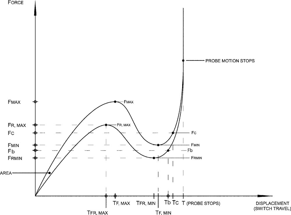
The following are a definition of terms in the diagram:
Force Terms
- Fmax: Maximum force measured prior to or including Fmin
- Frmax: Maximum force measured during return cycle after achieving Frmin
- Fmin: Minimum force seen between Fmax and the point at which the probe movement ceases
- Frmin: Minimum force seen during return cycle before reaching Frmax
- Fc: Contact force – the force at contact closure
- Fb: Break force – the force at contact break
Displacement (travel) terms
- Tfmax: Displacement at Fmax
- Tfrmax: Displacement at Frmax
- Tfmin: Displacement at Fmin
- Tfrmin: Displacement at Frmin
- Tc: Contact displacement – the displacement at contact closure
- Tb: Break displacement – the displacement at contact break
Teasing
- Switch teasing (make): The displacement measurement on the force displacement curve between contact force (Fc) and minimum force (Fmin)
- Switch teasing (break): The displacement measurement on the force displacement curve between contact break (Fb) and return force (Frmin)
Life Cycle Testing
Dome Mechanical Cycle Testing:
Setup
- Domes are tested on a hard flat steel surface perpendicular to the actuator test probe.
- The actuator test probe is a Delrin plastic and is centered over the dome within +/-0.015” [0.381mm].
- Dome is attached by a means of plastic tape using pressure sensitive adhesive and MUST provide venting for the dome.
Testing
- The test to run continuously at approximately 3-12 cycles per second.
- Actuator test probe at a diameter of approximately 25% of dome diameter.
- Maximum test force load is calculated as follows: Dome trip force + Trip force tolerance + 50 grams = Test Force (ex. F08400: 400+30+50 = 480 maximum test force)
- Life testing is performed in accordance with ASTM F1578 (Standard practice for contact closure cycling of a membrane switch) less electrical resistance testing.
Failure
- Failure is defined as the dome cracking before the specified cycle rating.